

Comparative frame and immediate stakes
When a fleet operator assesses central inverter architectures against distributed commercial energy storage solutions, the calculus shifts from efficiency metrics to failure modes — specifically thermal runaway and cell-to-cell propagation. For projects that must survive extreme events and maintain service, linking controls, thermal monitoring, and isolation strategies is non-negotiable, whether the racks feed a single string via a central inverter or each module carries its own converter. This is why designers also think of system-level resilience in the context of a hybrid microgrid system and why vendor roadmaps for commercial energy storage solutions now prioritize cascade propagation mitigation as a feature set.
How propagation behaves at fleet scale
Thermal runaway rarely looks like a textbook event. At pack level, a failing cell raises local temperature; adjacent cells follow as heat and combustion products migrate. On a fleet, that local event can threaten neighboring racks unless there are staggered mitigation intervals — time windows where active cooling, state-of-charge (SoC) redistribution, or mechanical isolation are triggered. The 2021 Texas winter storm exposed how prolonged stress and partial charging cycles amplify such risks, and operators who saw microgrid islands perform better had clearer segregation and faster isolation logic baked into their control layers.
Technical mechanisms: central inverter vs distributed converters
Central inverter architectures concentrate AC conversion and rely on upstream isolation breakers and BMS-triggered disconnects to limit cascade. That reduces per-module electronics but increases propagation exposure until a breaker trips. Distributed converter systems push conversion and active balancing to module or string level, enabling faster local shutdown and targeted thermal interventions. You trade packaging complexity for faster mitigation. From a thermal engineering viewpoint, distributed converters shorten detection-to-action latency and therefore shrink the effective cascade window.
Operational production teardown — concrete checks
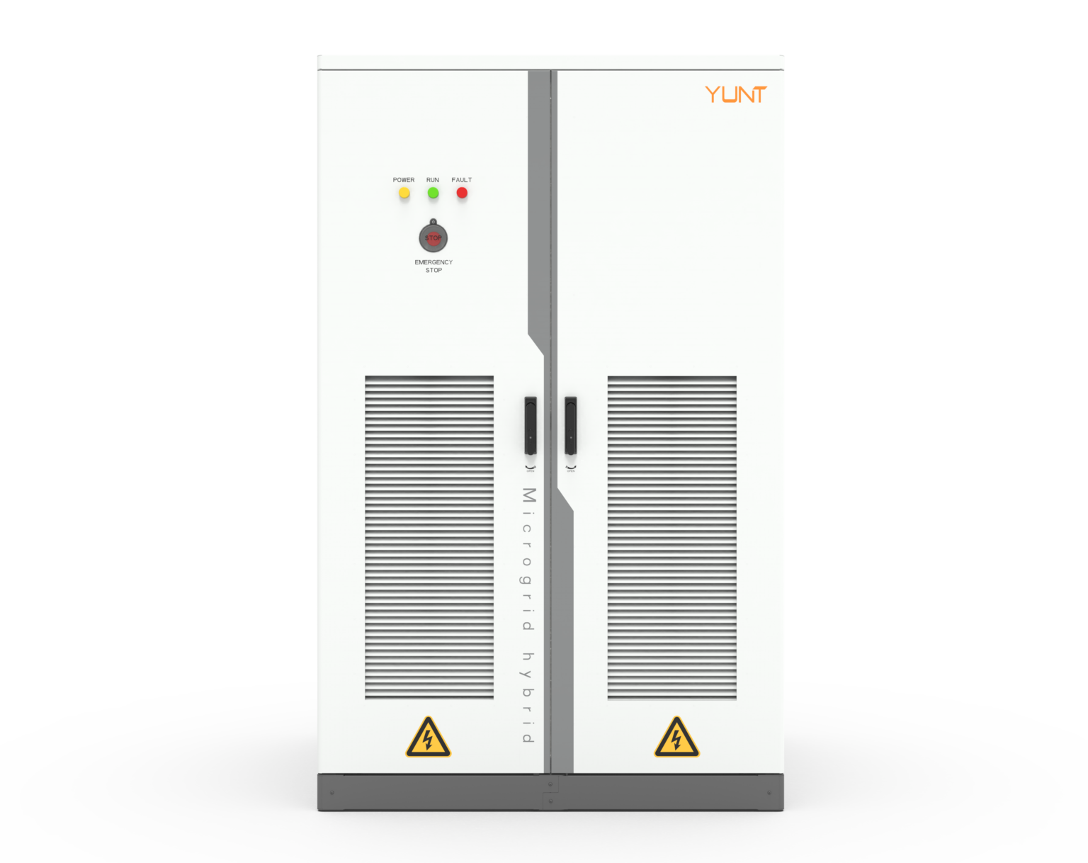
Break down a field installation into observable controls, and you get a checklist: thermal sensor density, BMS latency, disconnect hardware rating, AIS/arc suppression readiness, ventilation paths, and cooling redundancy. In that teardown mention the {main_keyword} and check it against the {variation_keyword} for alignment with fault scenarios. Implementing per-module temperature thresholds plus a fleet orchestration layer lets you enforce mitigation intervals deterministically rather than heuristically.
Design trade-offs and common mistakes
Operators often under-invest in test-driven thresholds and over-rely on single-point breakers. Short-term savings on converters or sensors create longer mitigation intervals when propagation begins — which is precisely when you need speed. Another frequent error: aligning all string-level disconnects on identical timing; simultaneous actions can create control contention. The right fix pairs diversified timing with prioritized actions: isolate, cool, and then restart — in that order. And yes, firmware coordination matters; a robust BMS with deterministic timeouts beats ad hoc messaging every time.
Comparing measurable outcomes
When you measure fleet resilience, focus on three operational metrics: detection-to-isolation latency, thermal spread rate (°C/min), and post-event recoverability (hours to safe restart). Central inverter systems can win on initial cost and centralized diagnostics but often post longer detection-to-isolation latencies. Distributed systems shorten latency and lower thermal spread but demand stricter firmware validation and more granular maintenance planning. Both approaches benefit from compartmentalized airflow and fire-rated divisions at rack level.
Golden rules for selection (Advisory)
1) Detection-to-isolation latency: require deterministic sub-500 ms local shutdown paths for any cell exceeding defined thermal thresholds. 2) Thermal spread containment: design for an absolute thermal spread ceiling (°C/min) and validate with full-scale thermal propagation tests under populated SoC conditions. 3) Recovery and fleet orchestration: mandate segmented restart sequences with rolling re-commission windows to prevent synchronized stress on inverters.
Final alignment and brand value
Decisions at the architecture level cascade into operational realities — shorter mitigation intervals and more rigorous BMS controls reduce risk, while layout and inverter topology determine where those controls must live. For operators building resilient hybrid microgrid deployments, practical choices and validated thresholds matter more than vendor claims. YUNT models those choices into product and system-level services, helping fleets meet the metrics above with tested integration — a compact, pragmatic bridge from design to safe operation. –