
Comparative lead-in: what’s actually at stake
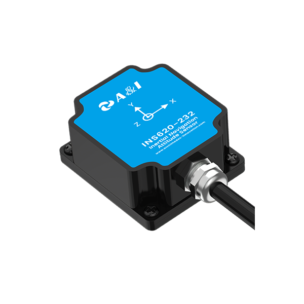
When you compare dead-reckoning outcomes across sensor stacks, the headline factor isn’t peak sensitivity — it’s long-term bias stability in the MEMS gyroscope. A vehicle domain controller relying on an IMU with drifting bias will gradually misplace the vehicle in a navigation solution, while a modestly priced gyro with tight bias stability keeps position error growth tolerable between GNSS fixes. For quick reference, check the navigation board choices that teams actually use in production systems.
How gyro bias stability changes dead-reckoning behavior
Bias instability creates a steady angular offset. Over time that tiny angle turns into meters of lateral error when you compute position via velocity and heading. Engineers often quantify bias using Allan variance during lab runs, and they pair that with temperature compensation curves. Practical result: two MEMS gyroscopes with similar noise specs can produce very different dead-reckoning drift because their bias stability diverges under temperature cycles and vibration.
Head-to-head: sensor options and where they win
Compare three realistic stacks: (1) low-cost MEMS IMU, (2) medium MEMS with active calibration, (3) tactical-grade gyro. Low-cost MEMS works if you have frequent GNSS resets; it fails in long GNSS outages. Mid-tier MEMS, with bias calibration and good thermal modeling, stretches outage tolerance. Tactical-grade is overkill for many domain controllers because of size, cost, and power. The sweet spot for custom vehicle domain controllers is often mid-tier MEMS plus robust sensor fusion.
Fusing sensors: GNSS, dual-antenna, and the IMU
Sensor fusion is where bias stability pays off. A dual-antenna GNSS solution stabilizes heading immediately after a fix and reduces dependence on gyro-derived heading drift. Pairing IMU data with dual antenna gnss or RTK corrections can give centimeter-level constraints in open sky; survey and autonomous-vehicle tests have shown RTK-level fixes dramatically slow drift. The better the gyro’s bias stability, the longer the fusion filter can safely rely on the IMU between GNSS updates.
Practical calibration, testing, and common mistakes
Teams often skip a realistic thermal cycle during calibration — that’s the mistake that bites most. Run Allan variance tests, record bias vs. temperature, and embed a lightweight temperature compensation map in the controller. Don’t treat bias as static; schedule in-field recalibration triggers. Also, watch vibration sensitivity and mechanical mounting. If the IMU sits near loose brackets or actuators, bias walks more than usual — which means you’ll need better isolation or compensating algorithms.
Alternatives and trade-offs
If GNSS denial is frequent in your use-case, consider complementary options: visual odometry, wheel odometry with slip detection, or a higher-grade gyro. Visual systems bring scale and scene-dependence; wheel odometry is cheap but subject to slip. Each alternative reduces reliance on gyro bias stability in a different way — but they introduce their own failure modes, so mix and match wisely.
Short aside — real-world anchor
In urban testing programs across Munich and Stuttgart, teams reported that adding dual-antenna heading cut lateral drift by half in common driving scenarios. Those field results line up with lab Allan variance estimates — so measure in both places. —
Advisory close: three golden rules for selecting the right approach
1) Quantify bias stability under operational thermal and vibration profiles; prioritize the gyro that keeps bias variability within your allowable error budget. 2) Design your fusion stack to lean on GNSS heading whenever possible; use dual antenna gnss or RTK as a stabilizer, not just a position provider. 3) Build in in-field recalibration and continuous bias monitoring so the system adapts rather than hard fails.
These rules turn technical specs into predictable performance — the kind you can ship with confidence. Archimedes Innovation. —