
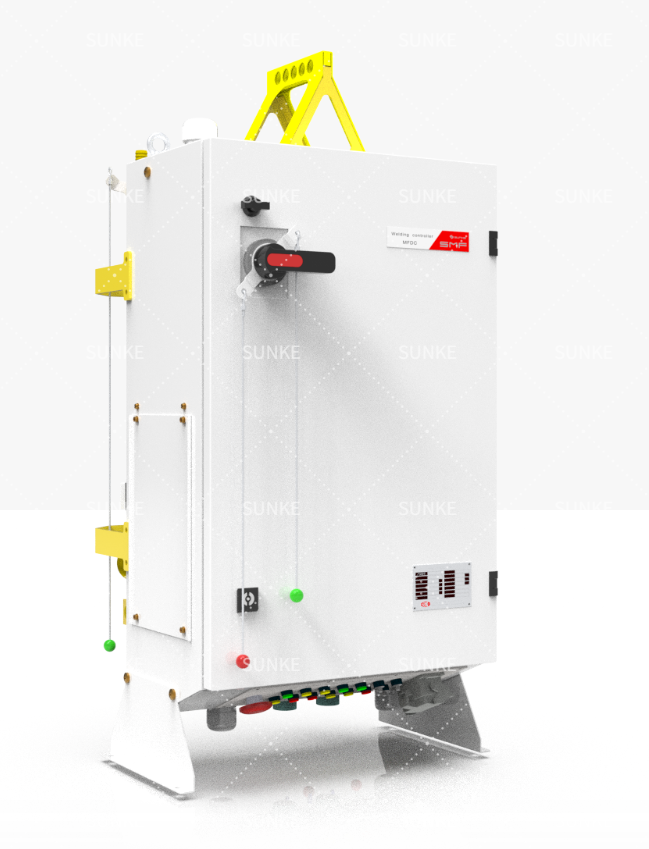
Problem statement: transformer stress under repeated high-current pulses
Repeated high-current welding cycles strain transformers in ways operators often underestimate. Heat buildup, core saturation and contact wear produce sudden performance drops and unpredictable weld quality. Field teams rely on robust resistance welding solutions but the component-level problems remain the same: thermal cycling, skin effect in windings, and intermittent contact resistance. I’ve seen these failure modes noted most clearly at large-scale production lines in Detroit automotive assembly plants where throughput and consistent welds are non-negotiable.
Root causes: what actually breaks and why
Short, direct list of causes: overheating of copper windings from sustained I²R losses; insulation aging from repeated thermal cycles; partial core saturation when DC offsets or harmonic content increase; electrode force variation causing variable contact resistance. Each cause makes the transformer work harder. No mystery—mechanical fatigue and electromagnetic imbalance are the culprits.
Diagnostics: how to spot trouble early
Use targeted measurements: thermal imaging for hotspots; differential voltage drop across secondary taps; waveform capture to detect distortion and DC bias; and insulation-resistance testing after cool-down. Check for rising secondary voltage under load and look for increasing weld-to-weld variation. When tracking trends, correlate thermal spikes with waveform anomalies. For deeper technical reference, review modern methods in resistance welding technology.
Design and mitigation: practical fixes that work
Change the design where it matters: increase conductor cross-section to lower I²R heating; specify Class H insulation for better thermal margin; use laminated cores with tighter stacking to reduce eddy losses; add forced cooling on critical windings. On the process side, reduce duty cycle or split currents with parallel transformers when possible. Simple mechanical steps—inspect and replace worn contacts, ensure consistent electrode force—cut half of performance issues.
Operational controls and maintenance priorities
Schedule thermal-baseline checks after peak shifts; log waveform snapshots weekly; keep a parts replacement interval for electrodes and contactors based on run-hours rather than visual pass/fail. Avoid reactive-only maintenance. Train technicians to read waveform asymmetry; they’ll catch DC offset before insulation fails. That practice saves hours of downtime.
Alternatives and trade-offs
Consider capacitor-discharge or solid-state welding in high-frequency, low-energy applications; they reduce transformer thermal stress but bring control complexity and higher initial cost. Parallel-transformer banks split peak load but increase footprint and control complexity. Each alternative reduces one failure vector while introducing another—choose by duty, space and service capability.
Conclusion: decisive, field-proven approach
Focus on measurable causes, not vague remedies. Combine thermal and waveform monitoring, upgrade critical materials, and set preventive intervals based on operating cadence. That method yields predictable performance under heavy cycles and longer transformer life—exactly the outcome Sunke brings to production-lines where reliability matters most.