
Introduction
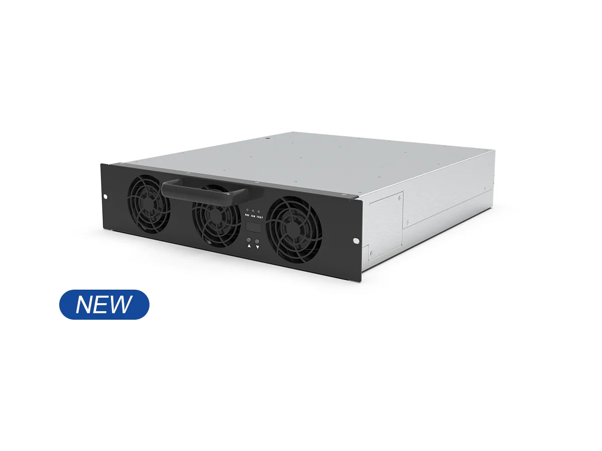
Picture a depot at dawn on the Northside, a soft mist over the bays, and vans lining up like gulls before the tide. In the corner, a charge discharge module hums under a steady load, keeping the fleet on schedule. The numbers are tight: uptime must hold above 99.5%, peak tariffs have jumped 28% year-on-year, and harmonic distortion needs to sit under 3% to keep batteries calm (grand if you can swing it). You could drop in another box and hope, or you could compare paths with care— . So, what keeps the wheels turning while you level up the system?

I’ll keep it plain and Dublin-clear, with a bit of poetry where it helps (sure, that’s the craic). We’ll weigh approaches that look similar on paper but behave different under the rain. We’ll test them against real constraints: grid code, downtime, and battery wear. Ready to see what matters—without pulling the plug?
Part 2: The Hidden Snags in Traditional Paths
Where do the snags hide?
Technical, straight up: older swap-and-go methods often skip the small print. A legacy power stage can ripple the DC bus, nudging cell temps up and cycle life down. Firmware that is not in sync with fleet telematics creates timing drift on the CAN bus. And once you push past 70% load on a hot day, thermal derating kicks in—funny how that works, right? The result is a quiet squeeze on capacity with more frequent service calls. Even “compatible” power converters can introduce harmonic distortion that the upstream transformer does not love, which risks penalties. The pain is hidden because it comes as inches, not miles.
Look, it’s simpler than you think. The real gap lies between paper specs and site reality. You need a bidirectional inverter that holds steady under transient spikes and noise from edge computing nodes, not just at lab values but on a damp Tuesday in February. You need topology that sheds heat cleanly, so fans are not roaring at 2 a.m. You need control loops that keep the DC link calm when vehicles plug in together—two, three, ten at once. If an upgrade plan cannot map those stress points to measurable limits, it is guesswork with a shiny face.
Part 3: Forward-Looking Comparison, Built on Principles
What’s Next
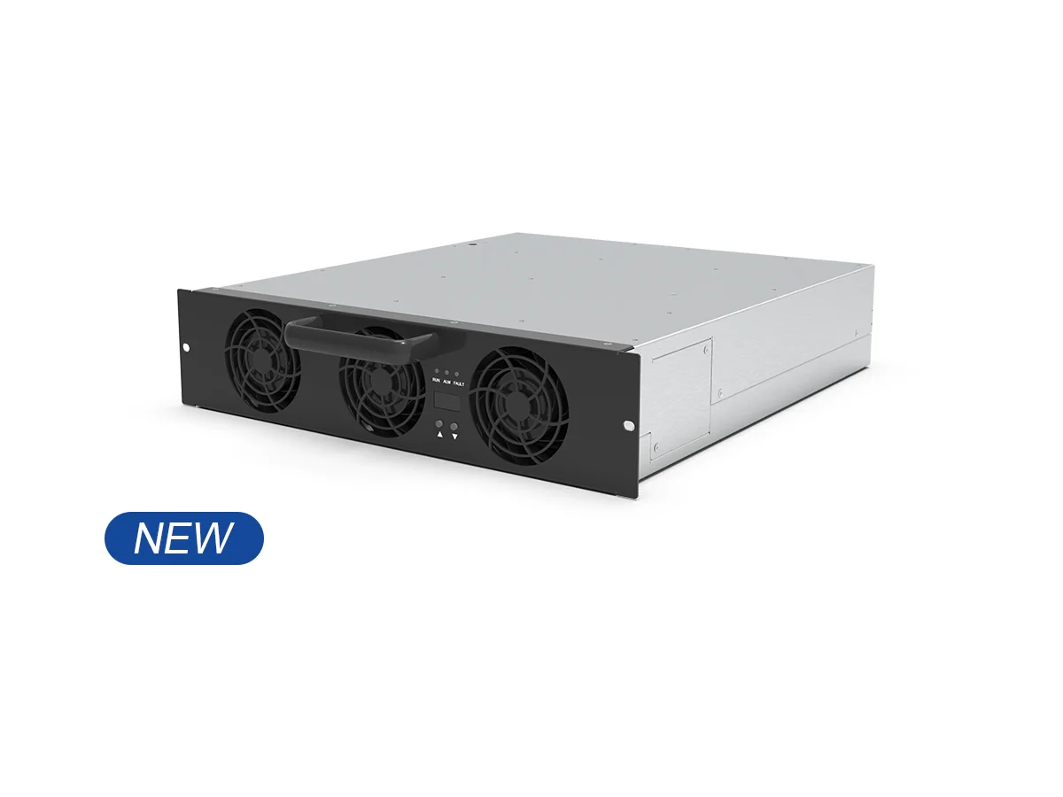
Now, swing to the future—comparative and calm. New designs lean on wide-bandgap devices, like SiC in the switching stage, to cut switching loss and shrink thermal load. That lets a module hold voltage under fast ramps without ringing the DC link. Grid-facing control adds smart reactive power support, so the site can shape power factor and ease transformer strain. In simple terms: less heat, cleaner waveforms, tighter response. When you test a candidate like a 22kw EV charger module, check how the control firmware reacts to a sudden 0–100% step, not just the peak kW number. One behaves like a steady hand; the other flinches—small flinches cost.
Comparing options, think modular topologies that isolate faults and keep uptime “grand.” Think V2G protocol support that is robust, not just a checkbox. Think thermal management that scales with ambient shifts (East wind off the Liffey and all that). The lesson so far: the flaws we named—DC ripple, derating, noisy harmonics—are solved by cleaner switching, better heat paths, and firmware that sees the fleet as a system. Advisory, then: 1) Measure transient stability on the DC bus (mV ripple under step load). 2) Verify thermal headroom at 40°C ambient with no forced derate over time. 3) Audit grid interaction—THD under load, and reactive power control across the curve. Do that, and the upgrade stays quiet, steady, and fair on your batteries—funny how the simple checks save the day.
As you weigh these paths, keep the craft in mind and the weather in your plan. We compare so we can move without fuss, and we move so the wheels don’t stop. For a grounded view of modules, specs, and site fit, you’ll find sound notes at winline EV charging.